14+ mr-101/cr wiring diagram
Honda crv diagram engine motor mount transmission accord 2001 1999 system wiring 4l exhaust roca rc schematic. This commit does not belong to any branch on.

Fibox Euronorm Elmatik As
7a 30vdc 10a 125vac 7a 250vac inductive.
. The Manufacturers shop drawing submittal. I got the most information from the BL Touch wiring website. CR-10 Circuit diagram Motherboard CR-10 Motherboard Wiring Diagrampdf Go to file Go to file T.
Data Sheet S270062 -- MR-100 200 Multi-Voltage. Wiring diagram badland 2000 lb winch wiring diagram. Dry form C SPDT per module.
The MR Series Multivoltage Control Relays offer SPDT or DPDT 10 Amp resistive contacts which may be operated by one of four input control voltages. Wiring and application diagrams mr-200 series mr-100 series wiring load power source load-n ac ac-n caution. De-energize all power before installation or service.
The MR-101C is a 24VDC MR Series Relay with SPDT 10A contacts. The 2x board is the most common for these printers. Each relay position contains a red LED which.
MR-101CRMR-101 MR-104CR MR-204T Coil Voltage MR-100. Air Products Controls MR-201CR. Diagram wiring journey stereo dodge infotainment SM_2215.
2002 Honda Cr V Wiring Diagram Fuse Box And Wiring Diagram. 35 Beautiful Fantastic Fan Wiring. Electrical Wiring Yamaha 703.
Mr 101 cr wiring. Copy path Copy permalink. WIRING AND APPLICATION DIAGRAMS ON REVERSE SIDE MR-100 SERIES PRODUCT SPECIFICATIONS.
Provide four 4 indexed and bound copies of all maintenance manuals wiring diagrams control panel interconnect diagrams and the individual. 21 posts related to Creality Cr 10 Wiring Diagram. Installation Wiring TYPICAL FOR ONE MODULE POSITION MR101 MR104 MR201 MR204 Specifications Ordering Information.
4l60e Transmission Wiring 4l60 Wiring Diagram. Mr 101 cr wiring diagram QSTIONCO - c general wire spring co. A single relay energized from a voltage source or VAC by wiring to appropriate input terminals.
Wiring diagram alternator bosch regulator generator internal voltage wire vw regulated electric gm circuit internally light motor warning converting wallace. Go to line L. Control 4 Wiring Diagramcontrol 4 Wiring Diagram.
Mr 101 cr wiring diagram. A single relay may be energized from a voltage source of 24VDC 24VAC 120VAC or 230VAC by wiring to appropriate input terminals. 20 21 22 are the same layout or very similar.
Of 24VDC 24VAC 120VAC or 230VAC by wiring to appropriate input terminals. Not shown in the instruction manual.
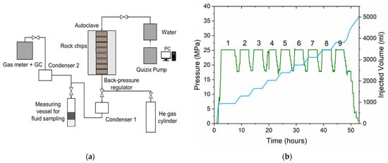
Energies Free Full Text Cyclic Subcritical Water Injection Into Bazhenov Oil Shale Geochemical And Petrophysical Properties Evolution Due To Hydrothermal Exposure Html
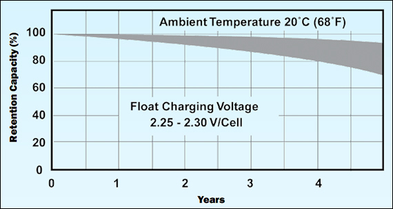
Bu 403 Charging Lead Acid Battery University
Crutchfield Readyharness Service Let Us Connect Your New Radio S Wiring To The Wiring Harness For Your Vehicle At Crutchfield

Functional And Biomimetic Materials For Engineering Of The Three Dimensional Cell Microenvironment Chemical Reviews

250ma Dc7 2v Output Csdn

Ultraviolet Photodissociation Mass Spectrometry For Analysis Of Biological Molecules Chemical Reviews
Gaining Control Over Conjugated Polymer Morphology To Improve The Performance Of Organic Electronics Chemical Communications Rsc Publishing Doi 10 1039 D2cc01430k

New Honeywell Mr 101 C R Multi Voltage Control Relay 814498022044 Ebay

Pdf Chm 001 Access Chemistry Course Development Course Developers Course Co Ordinators Designer Ifeanyi Nicodemus Academia Edu

New Honeywell Mr 101 C R Multi Voltage Control Relay 814498022044 Ebay
Bo 189 Hi Res Stock Photography And Images Page 3 Alamy

Fire Lite Mr 101t Data Sheet Pdf Relay Electronics

Electrically Conductive Metal Organic Frameworks Chemical Reviews

Mr 101 Cr Fire Lite
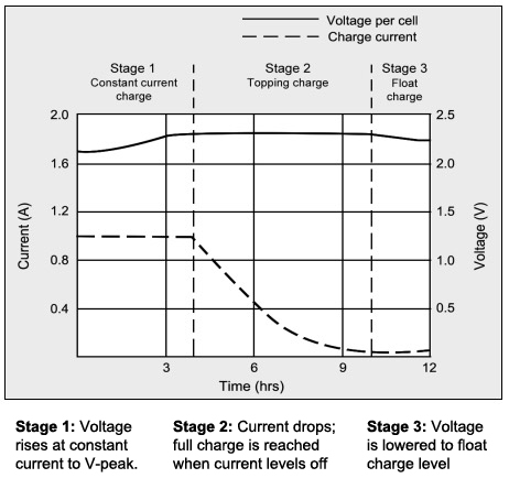
Bu 403 Charging Lead Acid Battery University

Hydrogen Deuterium Exchange In Mass Spectrometry Kostyukevich 2018 Mass Spectrometry Reviews Wiley Online Library

Fire Lite Mr 101t Data Sheet Pdf Relay Electronics